Electronic equipment in the use of a large number of various types of electronic components, equipment failure is mostly due to electronic component failure or damage caused. Therefore, how to correctly detect electronic components appears to be particularly important, this is also the electronic maintenance personnel must master the skills. In the electrical appliances maintenance has accumulated part of the common electronic components detection experience and skills.
1. Measure the polarity of each leg of the rectifier bridge.
Multimeter set R × 1k stop, black watch pen then bridge any pins, red watch pen has measured the remaining three feet, if the readings are infinity, then the black watch pen is connected to the positive output of the bridge, if the readings are 4 ~ 10kΩ, then the black watch pen is connected to the negative output of the bridge pile of pins, the remaining two pins for the AC input of the bridge.
2. Judge the quality of the crystal
First with a multimeter (R × 10k stop) measure the resistance of the crystal at both ends of the value, if infinity, that the crystal without short circuit or leakage; and then the test pen into the utility jack, pinch the crystal with your fingers any of the pins, will touch the other pins of the top of the metal part of the test pen, if the test pen neon bubble red, that the crystal is good; if the neon bubble is not bright, it indicates that the crystal is damaged.

3. One-way thyristor detection
Available multimeter R × 1k or R × 100 stop to measure the positive and negative resistance of any two poles, if you find a pair of poles resistance is low resistance (100Ω ~ lkΩ), then the black watch pen is connected to the control pole, the red watch pen is connected to the cathode, the other extremely anode. Thyristor has three PN junction, we can judge its good or bad by measuring the PN junction positive and negative resistance. When measuring the resistance between the control pole (G) and cathode [C], if the positive and negative resistance is zero or infinity, it means that the control pole is short-circuited or broken; when measuring the resistance between the control pole (G) and anode (A), the positive and negative resistance readings should be large;
When measuring the resistance between the anode (A) and cathode (C), both positive and negative resistance should be large.
4. Bi-directional thyristor polarity identification
A bi-directional thyristor has a main electrode 1, a main electrode 2 and a control electrode, and if the resistance between the two main electrodes is measured with a multimeter R×1k stop, the reading should be approximately infinity, while the positive and negative resistance between the control electrode and either main electrode reads only a few tens of ohms. Based on this characteristic, we can easily identify the control electrode of a bi-directional thyristor by measuring the resistance between the electrodes. And when the black watch pen connected to the main electrode 1. The red watch pen connected to the control electrode when the measured forward resistance is always smaller than the reverse resistance, according to which we can easily identify the main electrode 1 and the main electrode 2 by measuring the resistance.
5. Check the quality of the luminous digital tube
Multimeter placed R × 10k or R × l00k stop, and then the red table pen and digital tube (to the common negative digital tube as an example), the “to” terminal connected to the black table pen followed by other digital tube terminal, seven sections should be luminous, otherwise the digital tube is damaged.
6. Determine the junction type field effect tube electrode
Put the multimeter in the R × 1k stop, with a black pen contact is assumed to be the gate G pin, and then use the red pen to contact the other two pins, if the resistance value are relatively small (5 ~ 10 Ω), and then the red and black pen exchange measurement once. If the resistance values are large (∞), it means that both are reverse resistors (PN junction reverse), belongs to the N-channel tube, and the black watch pen contact the pin for the gate G, and explain the original assumption is correct. If the measured resistance are small again, it means that it is a positive resistance, belongs to the P-channel FET, the black watch pen is also connected to the gate G. If the above does not happen, you can swap red, black watch pen, according to the above method of testing, until judging the gate. General junction type FET source and drain in the manufacture of symmetrical, so when the gate G to determine the later, for the source S, drain D do not necessarily discriminate, because these two poles can be used interchangeably. The resistance between the source and drain is a few kilohms.
7. Identification of transistor electrodes
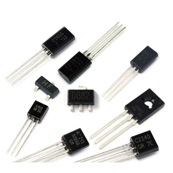
For a model labeled or unmarked triode, to distinguish their three electrodes can also be used to test a multimeter. First, the multimeter range switch on the R × 100 or R × 1k resistor stop. If the measured resistance is a few hundred ohms low resistance, then the electrode contacted by the red pen is the base electrode b, this tube is a PNP tube. If the measured resistance is tens to hundreds of kilohms of high resistance, the red pen contact electrode is also the base electrode b, this tube is an NPN tube.

On the basis of discerning the tube type and base b, the collector is determined by using the principle that the forward current amplification factor of the transistor is larger than the reverse current amplification factor. Either assume that one electrode is pole c and the other is pole e. Dial the multimeter range switch on the R x 1k resistor stop. For: PNP tube, so that the red pen connected to the c pole, black pen connected to the e pole, and then pinch the hand at the same time the b, c pole of the tube, but can not make the b, c two poles directly touching, measured a resistance value. Then the two pens for the second measurement, the two measured resistance compared, for the PNP type tube, the resistance value of a small one, the red pen electrode connected to the electrode as a collector. For the NPN type tube, the one with a small resistance value, the electrode connected to the black meter pen is the collector.
8. Determine the good and bad of potentiometer
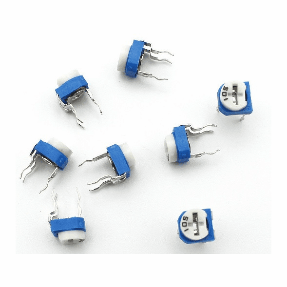
First measure the nominal resistance of the potentiometer. With a multimeter ohms measuring “1”, “3” ends (set “2” end for the active contacts), the reading should be the nominal value of the potentiometer, such as the multimeter pointer does not move, the resistance value does not move Or a large difference in resistance value indicates that the potentiometer is damaged. Then check whether the active arm of the potentiometer and the contact with the resistor is good. Use the ohmic stop of the multimeter to measure the “1”, “2” or “2”, “3” ends, turn the potentiometer’s rotor to the “1”, “2” or “2”, “3” ends. According to the counterclockwise rotation to close to the “off” position, the smaller the resistance should be the better, and then slowly clockwise rotation of the shaft handle, the resistance should gradually increase, rotary to the extreme position, the resistance should be close to the nominal value of the potentiometer. Such as the potentiometer shaft handle in the process of rotation of the multimeter pointer has beating coral like, tracing the activity of the kick contact ‘ poor contact.

9. Measure the leakage resistance of large capacity capacitors.
With a type 500 multimeter placed in the R × 10 or R × 100 stop, wait until the pointer points to the maximum, and then immediately change to use R × 1k stop measurement, the pointer will be stable in a shorter period of time, so as to read the leakage resistance value.
